Electric Motor Contactor Wiring Diagram . Looking for a 3 phase motor contactor wiring diagram? February 13, 2024 by damond goodwin. How to wire motor starters and contactors. This post reviews electrical contactor wiring, how electric contactors work, and introduces standard electrical contactor wiring diagram instructions. A contactor wiring diagram is a visual representation of the electrical connections and components used in a contactor circuit. This article investigates the basic. Contactors are used to provide this isolation. The circuit on the left is visually drawn based on the actual device. The complete guide of single phase motor wiring with circuit breaker and contactor or single phase motor contactor wiring diagram. Contactors use 120 volt standard power to energize a magnetic coil, which causes a set.
from manuallistjackshaft.z22.web.core.windows.net
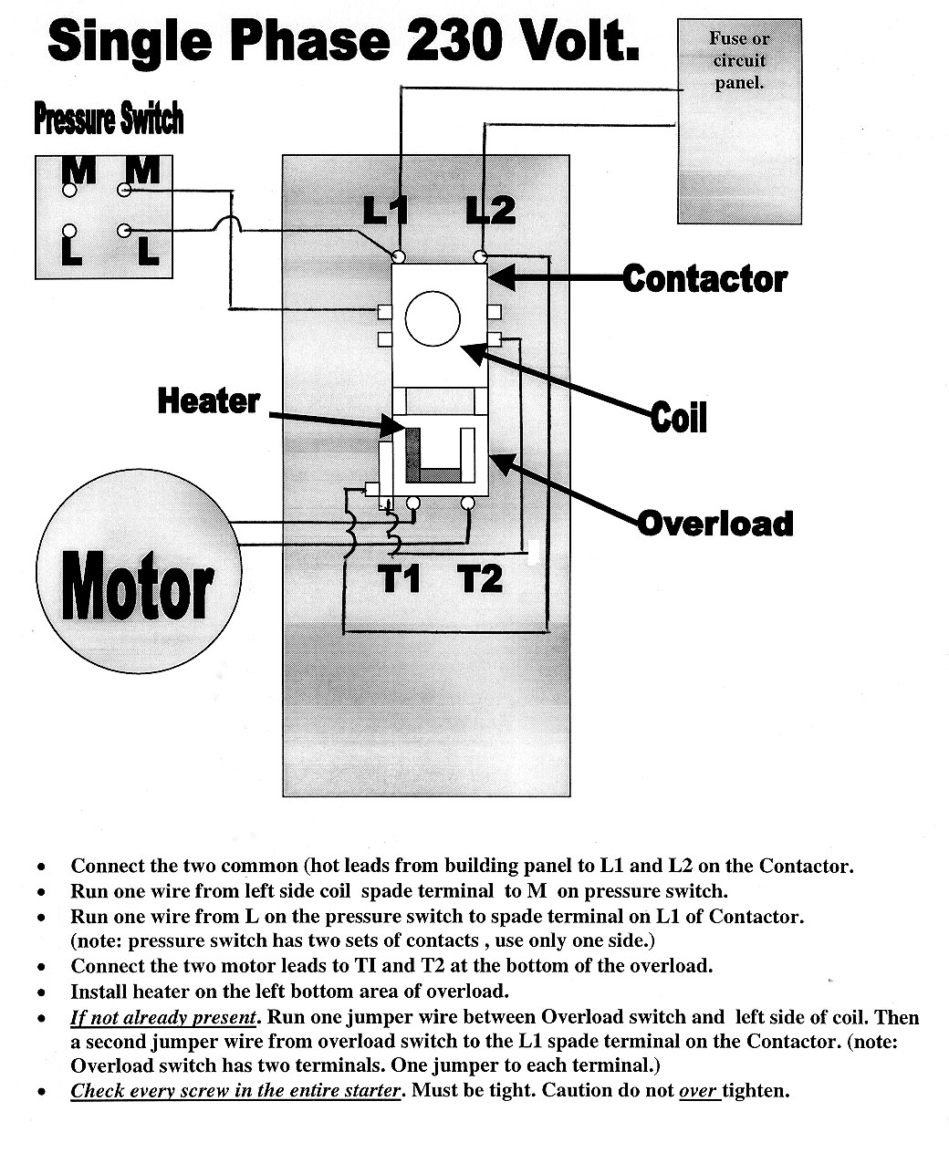
Looking for a 3 phase motor contactor wiring diagram? Contactors use 120 volt standard power to energize a magnetic coil, which causes a set. Contactors are used to provide this isolation. This post reviews electrical contactor wiring, how electric contactors work, and introduces standard electrical contactor wiring diagram instructions. The complete guide of single phase motor wiring with circuit breaker and contactor or single phase motor contactor wiring diagram. February 13, 2024 by damond goodwin. How to wire motor starters and contactors. This article investigates the basic. The circuit on the left is visually drawn based on the actual device. A contactor wiring diagram is a visual representation of the electrical connections and components used in a contactor circuit.
Electric Motor Wiring Diagram Single Phase
Electric Motor Contactor Wiring Diagram The circuit on the left is visually drawn based on the actual device. The complete guide of single phase motor wiring with circuit breaker and contactor or single phase motor contactor wiring diagram. How to wire motor starters and contactors. The circuit on the left is visually drawn based on the actual device. Looking for a 3 phase motor contactor wiring diagram? This article investigates the basic. A contactor wiring diagram is a visual representation of the electrical connections and components used in a contactor circuit. Contactors are used to provide this isolation. Contactors use 120 volt standard power to energize a magnetic coil, which causes a set. This post reviews electrical contactor wiring, how electric contactors work, and introduces standard electrical contactor wiring diagram instructions. February 13, 2024 by damond goodwin.
From circuitlistpedaled.z14.web.core.windows.net
Motor Wiring Diagram Explained Electric Motor Contactor Wiring Diagram Looking for a 3 phase motor contactor wiring diagram? The complete guide of single phase motor wiring with circuit breaker and contactor or single phase motor contactor wiring diagram. This post reviews electrical contactor wiring, how electric contactors work, and introduces standard electrical contactor wiring diagram instructions. A contactor wiring diagram is a visual representation of the electrical connections and. Electric Motor Contactor Wiring Diagram.
From elecengworld1.blogspot.com
Motor Contactor Wiring Diagram Electrical Engineering Blog Electric Motor Contactor Wiring Diagram This article investigates the basic. A contactor wiring diagram is a visual representation of the electrical connections and components used in a contactor circuit. The complete guide of single phase motor wiring with circuit breaker and contactor or single phase motor contactor wiring diagram. This post reviews electrical contactor wiring, how electric contactors work, and introduces standard electrical contactor wiring. Electric Motor Contactor Wiring Diagram.
From guidediagramimmigrants.z4.web.core.windows.net
Motor Wiring Diagram Single Phase Electric Motor Contactor Wiring Diagram Contactors are used to provide this isolation. The circuit on the left is visually drawn based on the actual device. How to wire motor starters and contactors. February 13, 2024 by damond goodwin. The complete guide of single phase motor wiring with circuit breaker and contactor or single phase motor contactor wiring diagram. This post reviews electrical contactor wiring, how. Electric Motor Contactor Wiring Diagram.
From schematicparttel.z21.web.core.windows.net
Schneider Contactor Wiring Diagram Pdf Electric Motor Contactor Wiring Diagram The circuit on the left is visually drawn based on the actual device. This post reviews electrical contactor wiring, how electric contactors work, and introduces standard electrical contactor wiring diagram instructions. A contactor wiring diagram is a visual representation of the electrical connections and components used in a contactor circuit. This article investigates the basic. Contactors are used to provide. Electric Motor Contactor Wiring Diagram.
From censerveiium.blogspot.com
TNB Get Electric Motor Contactor Wiring Diagram AZW Electric Motor Contactor Wiring Diagram Looking for a 3 phase motor contactor wiring diagram? Contactors use 120 volt standard power to energize a magnetic coil, which causes a set. How to wire motor starters and contactors. Contactors are used to provide this isolation. February 13, 2024 by damond goodwin. This post reviews electrical contactor wiring, how electric contactors work, and introduces standard electrical contactor wiring. Electric Motor Contactor Wiring Diagram.
From www.176iot.com
3 Phase Contactor Wiring Diagrams IOT Wiring Diagram Electric Motor Contactor Wiring Diagram The circuit on the left is visually drawn based on the actual device. The complete guide of single phase motor wiring with circuit breaker and contactor or single phase motor contactor wiring diagram. Contactors use 120 volt standard power to energize a magnetic coil, which causes a set. A contactor wiring diagram is a visual representation of the electrical connections. Electric Motor Contactor Wiring Diagram.
From wiringwiringlukas.z19.web.core.windows.net
Wiring A Contactor Diagram Electric Motor Contactor Wiring Diagram This post reviews electrical contactor wiring, how electric contactors work, and introduces standard electrical contactor wiring diagram instructions. How to wire motor starters and contactors. Looking for a 3 phase motor contactor wiring diagram? Contactors use 120 volt standard power to energize a magnetic coil, which causes a set. February 13, 2024 by damond goodwin. The complete guide of single. Electric Motor Contactor Wiring Diagram.
From circuitlibhomaged.z4.web.core.windows.net
Single Phase Motor Reversing Contactor Wiring Electric Motor Contactor Wiring Diagram How to wire motor starters and contactors. The complete guide of single phase motor wiring with circuit breaker and contactor or single phase motor contactor wiring diagram. This article investigates the basic. Looking for a 3 phase motor contactor wiring diagram? The circuit on the left is visually drawn based on the actual device. Contactors are used to provide this. Electric Motor Contactor Wiring Diagram.
From www.electricalonline4u.com
How To Wire Contactor And Overload Relay Contactor Wiring Diagram Electric Motor Contactor Wiring Diagram Contactors are used to provide this isolation. How to wire motor starters and contactors. A contactor wiring diagram is a visual representation of the electrical connections and components used in a contactor circuit. This post reviews electrical contactor wiring, how electric contactors work, and introduces standard electrical contactor wiring diagram instructions. The complete guide of single phase motor wiring with. Electric Motor Contactor Wiring Diagram.
From guidewiringsphincter.z14.web.core.windows.net
Wiring A 3 Phase Contactor Electric Motor Contactor Wiring Diagram How to wire motor starters and contactors. Contactors are used to provide this isolation. This post reviews electrical contactor wiring, how electric contactors work, and introduces standard electrical contactor wiring diagram instructions. Looking for a 3 phase motor contactor wiring diagram? Contactors use 120 volt standard power to energize a magnetic coil, which causes a set. A contactor wiring diagram. Electric Motor Contactor Wiring Diagram.
From wirelibrarybrahmins.z22.web.core.windows.net
Circuit Diagram Single Phase Electric Motor Electric Motor Contactor Wiring Diagram Contactors are used to provide this isolation. Looking for a 3 phase motor contactor wiring diagram? The complete guide of single phase motor wiring with circuit breaker and contactor or single phase motor contactor wiring diagram. This post reviews electrical contactor wiring, how electric contactors work, and introduces standard electrical contactor wiring diagram instructions. February 13, 2024 by damond goodwin.. Electric Motor Contactor Wiring Diagram.
From wiregram.homyracks.com
Understanding Single Phase Contactor Wiring Diagrams Wiring Diagram Electric Motor Contactor Wiring Diagram Looking for a 3 phase motor contactor wiring diagram? A contactor wiring diagram is a visual representation of the electrical connections and components used in a contactor circuit. Contactors are used to provide this isolation. February 13, 2024 by damond goodwin. This article investigates the basic. The circuit on the left is visually drawn based on the actual device. The. Electric Motor Contactor Wiring Diagram.
From guidediagramvillainess.z4.web.core.windows.net
Electric Motor Contactor Wiring Electric Motor Contactor Wiring Diagram This post reviews electrical contactor wiring, how electric contactors work, and introduces standard electrical contactor wiring diagram instructions. The circuit on the left is visually drawn based on the actual device. Contactors use 120 volt standard power to energize a magnetic coil, which causes a set. February 13, 2024 by damond goodwin. How to wire motor starters and contactors. Looking. Electric Motor Contactor Wiring Diagram.
From wiringwiringfrueh.z19.web.core.windows.net
Single Phase Contactor Wiring Diagram With Timer Electric Motor Contactor Wiring Diagram A contactor wiring diagram is a visual representation of the electrical connections and components used in a contactor circuit. This article investigates the basic. The circuit on the left is visually drawn based on the actual device. Contactors use 120 volt standard power to energize a magnetic coil, which causes a set. How to wire motor starters and contactors. Contactors. Electric Motor Contactor Wiring Diagram.
From schematiclistdrescher.z19.web.core.windows.net
3 Phase Contactor Circuit Diagram Electric Motor Contactor Wiring Diagram This post reviews electrical contactor wiring, how electric contactors work, and introduces standard electrical contactor wiring diagram instructions. Contactors use 120 volt standard power to energize a magnetic coil, which causes a set. The circuit on the left is visually drawn based on the actual device. The complete guide of single phase motor wiring with circuit breaker and contactor or. Electric Motor Contactor Wiring Diagram.
From wiredatakaravella4.z14.web.core.windows.net
3 Phase Contactor Wiring Schematics Electric Motor Contactor Wiring Diagram Looking for a 3 phase motor contactor wiring diagram? This post reviews electrical contactor wiring, how electric contactors work, and introduces standard electrical contactor wiring diagram instructions. Contactors are used to provide this isolation. The complete guide of single phase motor wiring with circuit breaker and contactor or single phase motor contactor wiring diagram. Contactors use 120 volt standard power. Electric Motor Contactor Wiring Diagram.
From fixenginesoothing.z14.web.core.windows.net
Electric Motor Wiring Diagram Troubleshooting Electric Motor Contactor Wiring Diagram Contactors are used to provide this isolation. Contactors use 120 volt standard power to energize a magnetic coil, which causes a set. This article investigates the basic. How to wire motor starters and contactors. Looking for a 3 phase motor contactor wiring diagram? The complete guide of single phase motor wiring with circuit breaker and contactor or single phase motor. Electric Motor Contactor Wiring Diagram.
From userlistfinkel.z19.web.core.windows.net
3 Phase Contactor Circuit Diagram Electric Motor Contactor Wiring Diagram This post reviews electrical contactor wiring, how electric contactors work, and introduces standard electrical contactor wiring diagram instructions. Contactors are used to provide this isolation. How to wire motor starters and contactors. The complete guide of single phase motor wiring with circuit breaker and contactor or single phase motor contactor wiring diagram. A contactor wiring diagram is a visual representation. Electric Motor Contactor Wiring Diagram.